
How to Choose the Right RF Coaxial Connector in 2026?

Choosing the right Rf Coaxial Connector in 2026 requires more than matching a familiar thread size. Frequency, impedance, power, environment, and installation quality must work together. A connector that performs well in a clean laboratory may fail beside a vibrating engine, outdoor antenna, or densely packed circuit board.

Dr. Paul G. Huray, a respected signal-integrity specialist, once stated, “A connector is part of the transmission line, not an afterthought.” That principle remains practical today. The connector’s body, dielectric, contact geometry, and shielding influence insertion loss, return loss, phase stability, and electromagnetic leakage. Even a small gap can become a serious problem at microwave frequencies.

Look closely.

Engineers should compare SMA, N-type, TNC, BNC, 2.92 mm, and other interfaces against the real operating conditions. Check the usable frequency range, voltage rating, mating cycles, cable compatibility, and sealing performance. A weatherproof N-type connector may suit a rooftop link, while a compact 2.92 mm option may better serve a high-frequency test fixture. The “best” choice is rarely universal.

Material selection matters, too. Gold-plated contacts resist oxidation, but plating thickness and manufacturing quality still require verification. Datasheets can appear convincing. Measurements may disagree. Use calibrated testing, including return-loss and insertion-loss checks, before approving a production design. Some recommendations may need revision after vibration, temperature, or repeated-mating tests. That is not failure; it is useful evidence.

This guide explains how to evaluate an Rf Coaxial Connector with clearer criteria, practical examples, and fewer assumptions. Expect trade-offs. Expect a few surprises.
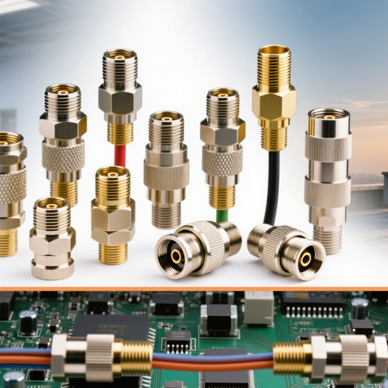
How to Choose the Right RF Coaxial Connector in 2026?

RF Coaxial Connector Basics and Key Performance Terms

How to Choose the Right RF Coaxial Connector in 2026?

RF coaxial connectors transfer high-frequency signals between cables, antennas, filters, and equipment. Their basic structure includes a center contact, dielectric, outer conductor, and metal body. Most systems use 50-ohm impedance, while video systems often use 75 ohms. Mixing them can increase reflections.

Key terms need practical attention. Return loss measures reflected energy; higher values usually indicate better matching. VSWR shows the same problem as a ratio, where 1.0:1 is ideal. Insertion loss measures signal power lost through the connector.

A 2024 global mobility report forecasts 5G subscriptions could reach 6.3 billion by 2029, increasing pressure on low-loss interconnections. For dense radio hardware, I would check the specified frequency range, not only the connector shape. A connector rated to 6 GHz may perform poorly near 18 GHz.

Power handling, shielding effectiveness, and passive intermodulation also matter. Poor contact pressure can create unwanted signals during transmission.

Mating cycles, vibration resistance, and temperature ratings should match the installation site. IEC 61169 provides a useful framework for connector dimensions and performance testing.

On the bench, I still inspect the cable termination twice. Small alignment errors can change the measurement. A perfect datasheet cannot rescue careless assembly.

Reports often emphasize market growth, but field reliability depends on details they cannot show: torque, cleanliness, plating wear, and repeated handling.

Define Your Frequency, Impedance, and Power Requirements

How to Choose the Right RF Coaxial Connector in 2026?

Define Your Frequency, Impedance, and Power Requirements

Start with the highest operating frequency, not the average frequency. A connector rated for 6 GHz may behave differently near its limit. At higher frequencies, small gaps, rough plating, and poor cable preparation can increase reflection and insertion loss. Check the connector’s frequency range, return loss, and voltage standing wave ratio. These figures reveal more than a simple “high-frequency” label.

Impedance must match the complete RF path. Most systems use 50 ohms, while many video systems use 75 ohms. Mixing them can create reflections, unstable measurements, and unwanted signal loss. I normally verify the equipment ports, cable, adapter, and termination before selecting a connector. Use a calibrated vector network analyzer when accuracy matters. A visual inspection alone is not enough.

Power requirements need careful definition. Record average power, peak power, pulse width, duty cycle, and operating frequency. A connector carrying brief pulses may tolerate more power than one carrying continuous energy. Temperature also matters. Heat reduces safe power capacity, especially inside compact enclosures. Check derating curves and mounting conditions in the technical datasheet.

I once treated a peak rating as continuous power, and that assumption was wrong. It is worth checking twice.

Connector size, locking method, environmental sealing, and service access also affect reliability. A technically suitable connector can still fail when technicians cannot tighten it consistently.

Match Connector Type, Interface, and Cable Dimensions

How to Choose the Right RF Coaxial Connector in 2026?

Choosing an RF coaxial connector starts with the connector type, not its appearance. Select threaded, bayonet, push-on, or blind-mate designs according to vibration, access, and service frequency. A connector used outdoors needs strong sealing and controlled mechanical tolerances. Indoor test equipment may prioritize quick changes and repeatable connections.

Match the interface exactly. Check impedance, gender, polarity, coupling style, and contact dimensions in the technical drawing. A 50-ohm system can suffer serious reflection when one interface is mismatched. Frequency rating also matters, especially in compact 2026 systems using higher microwave bands.

I once focused too much on frequency range and overlooked the mating interface. The assembly passed inspection, but installation was awkward. That mistake was avoidable.

Tips: Measure the cable before ordering. Record its outer diameter, dielectric size, center conductor diameter, and shielding structure. Then verify the connector’s cable range and recommended stripping dimensions. Do not force a connector onto a nearly compatible cable. It may fit. It may fail later. Leave enough bend radius behind the connector, and avoid twisting the cable during tightening. For critical links, confirm return loss and insertion loss with calibrated equipment. Manufacturer drawings, controlled test procedures, and batch inspection provide stronger evidence than a product photograph.

Evaluate Materials, Environment, and Installation Conditions

How to Choose the Right RF Coaxial Connector in 2026?

Connector selection starts with the environment, not the catalog photo. The Mobile Economy 2025 report forecasts 5.5 billion 5G connections by 2030. That growth will push more connectors into compact, crowded equipment. Check the operating frequency, impedance, and insertion-loss target first. A 50-ohm connector is unsuitable for a 75-ohm video path. Small mismatches can create visible signal reflections.

Material choice matters in real installations. Gold-plated contacts resist oxidation, while nickel-plated bodies often provide practical mechanical strength. Stainless steel can survive moisture, but it may increase cost and complicate machining. In outdoor cabinets, review salt spray, humidity, vibration, and temperature cycling. IEC 61169 defines important connector interface requirements, yet compliance alone does not guarantee field reliability. I have seen correct interfaces fail because a cable jacket softened near a hot enclosure.

Tips: Match the connector to the cable before ordering. Measure the panel cutout. Confirm the mating cycle rating. Use a torque wrench when specified. Keep the bend radius visible during installation. A weather seal may look sufficient, but poor compression can still admit moisture. Leave service access around the connector. Tight spaces invite damaged threads and uneven torque. Choose the shortest practical transition, although shorter is not always better when routing stress is ignored. Test return loss after assembly, not only before deployment.

How to Choose the Right RF Coaxial Connector in 2026? — Evaluate Materials, Environment, and Installation Conditions
Connector Type Typical Impedance Typical Frequency Range Common Contact and Body Materials Environmental Suitability Typical Installation Method Mechanical Characteristics Relative Environmental Robustness Selection Considerations
BNC 50 Ω or 75 Ω DC to approximately 4 GHz, depending on design Brass or stainless-steel body; gold-, nickel-, or silver-plated contacts; PTFE dielectric Suitable for indoor instrumentation and protected outdoor equipment when a sealed version is used Bayonet coupling; solder, crimp, or compression termination Fast quarter-turn mating; moderate vibration resistance Medium Choose the correct impedance version. Avoid standard unsealed parts in persistent moisture, salt spray, or heavy contamination.
TNC 50 Ω DC to approximately 11 GHz, depending on design Nickel-plated brass or stainless steel; gold- or nickel-plated contacts; PTFE dielectric Better suited than BNC for outdoor and mobile applications when properly sealed Threaded coupling; crimp, solder, or clamp termination Improved vibration resistance compared with bayonet-coupled connectors Medium to High A practical choice where vibration is present and a threaded interface is preferred without moving to a larger connector.
Type N 50 Ω or 75 Ω DC to approximately 11 GHz for common 50 Ω designs Brass, bronze, or stainless-steel body; silver-, nickel-, or passivated finishes; PTFE or other low-loss dielectric Well suited to outdoor infrastructure when using a sealed assembly and appropriate cable jacket Threaded coupling; crimp, clamp, or solder termination Strong mechanical interface with good sealing capability High A strong general-purpose option for antennas, base stations, and test equipment. Verify the exact frequency rating of the selected assembly.
SMA 50 Ω DC to approximately 18 GHz for standard designs; higher-performance versions may extend beyond this Stainless steel or brass body; gold-plated or passivated contacts; PTFE dielectric Suitable for controlled indoor use and sealed outdoor modules; exposed assemblies require environmental protection Threaded coupling; solder, crimp, or clamp termination Compact and high-frequency capable; small interface requires careful torque control Medium Use torque-controlled installation and avoid repeated mating beyond the connector’s specified mating-cycle life.
2.92 mm 50 Ω DC to approximately 40 GHz Stainless steel body; precision gold-plated or other specified contacts; precision PTFE or air dielectric Primarily intended for controlled laboratory, production-test, and protected system environments Precision threaded coupling; cable or test-fixture termination Very high electrical precision but comparatively delicate mechanical interface Low to Medium Select when phase stability and millimeter-wave performance are more important than field ruggedness. Keep mating surfaces clean and undamaged.
7/16 DIN 50 Ω DC to approximately 7.5 GHz, depending on design Brass or stainless-steel body; silver-, nickel-, or passivated finishes; PTFE or low-loss dielectric Highly suitable for outdoor cellular, broadcast, and high-power infrastructure when sealed correctly Large threaded coupling; clamp or solder termination High power handling, strong mechanical strength, and good passive intermodulation performance when correctly installed Very High Prefer this format for high-power transmit paths, exposed infrastructure, and applications requiring robust weather sealing.
MCX 50 Ω DC to approximately 6 GHz, depending on design Brass or stainless-steel body; gold- or nickel-plated contacts; PTFE or molded fluoropolymer dielectric Best for protected indoor or embedded applications; not normally selected for direct outdoor exposure Snap-on coupling; crimp or solder termination Very compact and quick to mate; lower mechanical retention than threaded types Low to Medium Useful where PCB density and compact size matter. Add cable strain relief because lateral cable movement can stress the interface.
MMCX 50 Ω DC to approximately 6 GHz, depending on design Brass or stainless-steel body; gold- or nickel-plated contacts; PTFE or molded fluoropolymer dielectric Typically used inside compact electronic equipment; environmental sealing depends strongly on the complete assembly Snap-on coupling; PCB, crimp, or solder termination Extremely compact with limited mechanical robustness under repeated cable movement Low Select for compact wireless modules and internal interconnects. Use a secured cable route and avoid treating it as a field-service connector.

Compare Reliability, Compliance, Cost, and Future Compatibility

How to Choose the Right RF Coaxial Connector in 2026?
Compare Reliability, Compliance, Cost, and Future Compatibility

In practical RF evaluations, reliability starts with the real operating environment. Check mating cycles, vibration, temperature, moisture, and cable movement. A connector may perform well on a bench but fail inside a vibrating cabinet. Measure insertion loss and return loss at the highest planned frequency. Do not trust a familiar part without recent test data.

Reliability
Compliance

Compliance deserves equal attention. Request material declarations, traceability records, and test reports for relevant electrical and environmental requirements. Confirm restricted-substance documentation for every production batch. Regional rules can change during a product’s service life. That detail is easy to miss.

Cost

Cost is more than the purchase price. A cheap connector can increase assembly time, rework, calibration, and field failures. Compare tooling, mating durability, inspection needs, and replacement access. Also verify whether technicians can install it consistently. Small differences matter.

Future compatibility needs careful judgment. Match impedance, interface geometry, frequency range, and cable dimensions before approving a design. Leave reasonable electrical margin above today’s requirement. Check whether the connector remains available, documented, and mechanically compatible with future assemblies. Modular designs can help, but they may introduce extra interfaces and losses. More flexibility is not always better. I have seen teams overbuy performance they never used, while underestimating supply risk. A second-source review early in development is wiser than a rushed redesign later.

Future Compatibility
dLED: retail LED lighting
Privacy Overview

This website uses cookies so that we can provide you with the best user experience possible. Cookie information is stored in your browser and performs functions such as recognising you when you return to our website and helping our team to understand which sections of the website you find most interesting and useful.